
Arduino Interactive Play Mat from Kendalf on Vimeo.
Thursday, November 7, 2013
Interactive Town Play Mat Complete
Here is a video featuring all three parts of the Interactive Town Play Mat.
Sunday, November 3, 2013
Train Crossing Signal with Ultrasonic Trigger

After several design iterations I finally completed the Train Crossing Signal for the Interactive Town Play Mat project. This portion of the project uses an ultrasonic sensor to trigger two model train signal lights that I found on eBay. The sensor sends out ultrasonic sound pulses, and then listens for the echo. The Arduino sketch includes a calculation that takes the time that it takes for the echo to return to calculate the range of the reflecting object.
In my sketch, when the sensor detects an object at close range (about 3 cm) it triggers the light flashing function. By placing the breadboard with the sensor right beside the track, the crossing signal will be triggered by a passing train. The function then performs a check to keep the lights flashing for the designated time interval, enough to allow the train to pass the crossing.

The breadboard circuit is diagrammed below. The crossing signal lights require a 12V power supply, so like the city street lights portion of the play mat, I had to incorporate transistors in the circuit.

Train Crossing Flashing with Ultrasonic Sensor.mp4 from Kendalf on Vimeo.
The Sketch:
/* Train Crossing Signal with Light Sensor
 by: Ken Yeh
 */

/* Pin Definitions */
int trigPin = 2;  // set Ultrasonic trigger pin
int echoPin = 3;  // set Ultrasonic echo detect pin
int ledPin1 = 5;  // LED 1
int ledPin2 = 6;  // LED 2
int buzzerP = 7;
int buzzerN = 12;

/* Global variables */
boolean ledState = false; //boolean variable used to store the current LED state
long previousMillis = 0; //stores the last time LED was updated
long interval = 350;  //time interval (in ms) between LED flash
long duration, distance; // Duration used to calculate distance
long signalDuration = 5000; // Time duration for signal to stay on after triggered
long startTime = -signalDuration; // stores when signal is triggered, set to a value to initially keep signal off

void setup()
{
  pinMode(ledPin1, OUTPUT);  // set LED pin as output
  pinMode(ledPin2, OUTPUT);
  pinMode(trigPin, OUTPUT);
  pinMode(echoPin, INPUT); // set Echo pin as input

  //Buzzer
  pinMode(buzzerP, OUTPUT);  // set both buzzer pins as outputs
  pinMode(buzzerN, OUTPUT);

  Serial.begin(9600);  // We'll output some information over serial
}

void loop()
{
  // Ultrasonic Sensor
  /* The following trigPin/echoPin cycle is used to determine the
     distance of the nearest object by bouncing soundwaves off of it. */
  digitalWrite(trigPin, LOW);
  delayMicroseconds(2);

  digitalWrite(trigPin, HIGH);
  delayMicroseconds(10);

  digitalWrite(trigPin, LOW);
  duration = pulseIn(echoPin, HIGH);

  // Calculate the distance (in cm) based on the speed of sound.
  distance = duration / 58.2;

  Serial.print("Range= ");
  Serial.println(distance);

  // Test if Signal should be activated
  if(distance < 5 && distance != 0)  //detects if train is within a certain range
  {
    startTime = millis(); // sets time for when the signal is triggered
    flashSignal();  // call the Signal Flashing function
  }
  else    // else turn signal off when no train is in range
  {
    digitalWrite(ledPin1, false);
    digitalWrite(ledPin2, false);
  }
}

// Signal Flashing Function
void flashSignal()
{
  while(millis() - startTime < signalDuration) // Keeps signals flashing for the set time duration
  {
    unsigned long currentMillis = millis();
    // Loop that causes the signal lights to flash alternatively at the set time interval
    if(currentMillis - previousMillis > interval)
    {
      previousMillis = currentMillis;    // save the last time you blinked the LED
      ledState = !ledState;   // toggle ledState
      digitalWrite(ledPin1, ledState);  // give LEDs opposite states
      digitalWrite(ledPin2, !ledState);
      // tone(7, 750, 100);    // need to test this for crossing signal sound
    }
  }
}
Friday, October 18, 2013
Dimmable LED Street Lights
What's a city play mat without street lights? These model train set street lights I purchased from eBay arrived and I incorporated them into the previous "Potentiometer Controlled LEDs" circuit.
 One complicating factor is that these LEDs operate on 12 Volts. Technically, it's the LED together with the attached 400 Ω resistor that requires 12V. Each LED also draws about 20mA of current, and a simple calculation using Ohm's Law (Voltage = Current x Resistance) yields the result that the resistor consumes about 8V leaving 4V for the actual LED itself. So if I had a 4V power source then I could cut off the resistor completely and power just the LED by itself, but since I already have a 12V power source ready I decided to just stick to "stock." Also, I plan to string together 10 of these street lights together, which would draw far more current than the max 40mA that each digital output pin on the Arduino is capable of. So an external power supply would be necessary anyway.
Here is the complete circuit showing how the PN2222 transistor and the potentiometer are connected to control the LEDs, powered by the external 12 Volt power supply:
 The Arduino sketch is the same as the earlier "Potentiometer Controlled LEDs," with analog input A1 reading the potentiometer and then translating that input to a PWM signal through digital pin 3.
Below are a couple pictures of the messy, but working prototype for this circuit.


The LEDs also lit up when I connected the power supply to them directly. I then remembered that I needed to have the all the components tied to a common ground, and one extra jumper from the GND pin of the Arduino to the breadboard pins that the negative wire of the power supply was connected to completed the circuit and the lights were able to be dimmed and controlled by the potentiometer.
Next step, actually mounting these lights to the play mat and wiring it up more neatly!

Transistors
However, the inclusion of an external power supply requires using a transistor in order to interface with an Arduino. This adafruit tutorial gives a great basic lesson on transistors. Essentially, the transistor acts as an electronic switch that allows a small current flow from the digital output of the Arduino to "switch on" a much larger flow of electricity (provided by the external power supply) through the circuit loop that the LEDs are connected to.| By Simon Monk, from http://learn.adafruit.com/assets/2348 |

Below are a couple pictures of the messy, but working prototype for this circuit.


Debugging
It actually took quite some time to get this circuit to finally work, and again a multimeter was invaluable in the debugging process. First, the multimeter helped me determine that my power supply (which was a 12 Volt "wall wart" that had the adapter end cut off, leaving separate + and - wires) went against convention and had the striped wire as negative, opposite to what I had determined with a quick Google search. But the LEDs still wouldn't light, so using the multimeter I was able to determine that proper signals were coming out from the Arduino.The LEDs also lit up when I connected the power supply to them directly. I then remembered that I needed to have the all the components tied to a common ground, and one extra jumper from the GND pin of the Arduino to the breadboard pins that the negative wire of the power supply was connected to completed the circuit and the lights were able to be dimmed and controlled by the potentiometer.
Next step, actually mounting these lights to the play mat and wiring it up more neatly!
Additional References:
bildr >> High-Power Control: Arduino + TIP120 transistorThursday, October 3, 2013
Potentiometer Controlled LEDs
Another part of my Interactive Town Play Mat project is a series of "street lights" along a few of the streets. I originally thought about using a light sensor that would automatically turn on the streets lights when the ambient light level grew dim (like a night light), but I decided to scrap this idea after several prototypes. The main problem was that the light sensor that came with the Lilypad ProtoSnap is very fidgety, in that the reading from the sensor fluctuates even at a constant ambient light level. If I set a certain light reading level (say, <50) as the trigger for when the LEDs would turn on, when the ambient light dropped near that level, the light sensor would continually flip above and below that threshold, causing the lights to flicker on and off. The sensor works fine for gross changes in light (like when the sensor is covered) but I could not figure out a way to effectively apply it with gradually dimming ambient light.
So instead I decided to incorporate a manual "dimmer" control to control the lights. This is accomplished through the use of a potentiometer.
The circuit is represented by the diagram below, made using the open-source software from Fritzing.org.
.png)
A brief video of how it works:
The full sketch is included at the bottom of this post for reference. The neat new function was using map(potReading, 0, 1024, 0, 255) to convert the analog readings from the potentiometer (ranging from 0-1024) to the output range for the digital pins (ranging from 0-255).
So I thought this would be a very straightforward circuit and sketch to create. The two tutorials I reference at the end of this post helped me understand how to read a potentiometer using an Arduino, and then how to output the signal to a string of LEDs. However, when I applied power to the circuit the first time, no LEDs turned on. I had set up the serial monitor to indicate both the potentiometer reading as well as the brightness level being sent to the LED, but turning on the serial monitor indicated readings of zero across the board.
Some debugging and browsing Arduino reference sites revealed that I had declared the potPin variable incorrectly. One of the tutorials I referenced used "const byte" to declare the variable for the analog pin that was reading the potentiometer, but apparently this would not work for the Uno because it used "A1" for the analog pin rather than just "1". Or something. Anyway, all I know is that when I switched to "const int" to declare that variable it worked, and I started getting readings through the serial monitor.
Unfortunately, the serial monitor output seemed to lag considerably behind what the potentiometer was set to, as in I could turn the pot full on but the serial monitor would still display a low value for several more seconds. I figured out that this was due to a bug in Codebender, and when I used the Arduino IDE the serial monitor kept in sync perfectly.
And while the serial monitor was showing the right values, for some reason the LEDs were still not lighting. It took me awhile to figure out that I had forgotten to turn on the little on/off slider switch that I had added to the circuit. DUH! This just goes to show that so many little things can cause a circuit to fail, and it's part of the challenge of electronics to follow the trail and try to find and fix every single little thing.
http://www.electroschematics.com/9009/led-brightness-fan-speed-arduino/
So instead I decided to incorporate a manual "dimmer" control to control the lights. This is accomplished through the use of a potentiometer.
The circuit is represented by the diagram below, made using the open-source software from Fritzing.org.
.png)
A brief video of how it works:
The full sketch is included at the bottom of this post for reference. The neat new function was using map(potReading, 0, 1024, 0, 255) to convert the analog readings from the potentiometer (ranging from 0-1024) to the output range for the digital pins (ranging from 0-255).
So I thought this would be a very straightforward circuit and sketch to create. The two tutorials I reference at the end of this post helped me understand how to read a potentiometer using an Arduino, and then how to output the signal to a string of LEDs. However, when I applied power to the circuit the first time, no LEDs turned on. I had set up the serial monitor to indicate both the potentiometer reading as well as the brightness level being sent to the LED, but turning on the serial monitor indicated readings of zero across the board.
Some debugging and browsing Arduino reference sites revealed that I had declared the potPin variable incorrectly. One of the tutorials I referenced used "const byte" to declare the variable for the analog pin that was reading the potentiometer, but apparently this would not work for the Uno because it used "A1" for the analog pin rather than just "1". Or something. Anyway, all I know is that when I switched to "const int" to declare that variable it worked, and I started getting readings through the serial monitor.
Unfortunately, the serial monitor output seemed to lag considerably behind what the potentiometer was set to, as in I could turn the pot full on but the serial monitor would still display a low value for several more seconds. I figured out that this was due to a bug in Codebender, and when I used the Arduino IDE the serial monitor kept in sync perfectly.
And while the serial monitor was showing the right values, for some reason the LEDs were still not lighting. It took me awhile to figure out that I had forgotten to turn on the little on/off slider switch that I had added to the circuit. DUH! This just goes to show that so many little things can cause a circuit to fail, and it's part of the challenge of electronics to follow the trail and try to find and fix every single little thing.
References:
http://www.arduino.cc/en/Tutorial/Potentiometerhttp://www.electroschematics.com/9009/led-brightness-fan-speed-arduino/
The Sketch:
/*
 Potentiometer Controlled Street Lights
 Sketch that adjusts the brightness of a string of LED lights
 based on analog readings of a potentiometer

 Created 9/30/13
 By Ken Yeh

*/

/*  Pin Definitions  */
const int potPin = A1;  // Potentiometer connected to analog input A1
const int ledPin = 3;     // LED connected to PWM pin 6
int potReading;   // Variable to hold the reading from the potentiometer
int ledBrightness;  // Variable that holds the LED brightness level

void setup()
{
 pinMode(ledPin, OUTPUT);
 pinMode(potPin, INPUT);
 Serial.begin(9600);
}

void loop()
{
 potReading = analogRead(potPin); // Read value from potentiometer
 ledBrightness = map(potReading, 0, 1024, 0, 255); // Converts analog reading from pot to 8-bit value
 analogWrite(ledPin, ledBrightness); // Output at this level for the LED
 Serial.print("Potentiometer=");
 Serial.print(potReading);
 Serial.print("   LED Level=");
 Serial.println(ledBrightness);
}
Tuesday, October 1, 2013
Traffic Signal Prototype
After achieving success with getting the RGB NeoPixels to work, I quickly put together a sketch to control a traffic signal for a four-way intersection.
This is what it looks like while running:
A few things that I learned while putting this together.
The full sketch is included at the bottom of this post for reference, but the code for controlling each NeoPixel is as simple as:
For example, in my traffic signal sketch, I declare these variables:
Judicious use of variables can greatly speed up the fine-tuning of a project.
This is what it looks like while running:
A few things that I learned while putting this together.
1. NeoPixels are awesome!
My original intent in using NeoPixels rather than separate Red, Yellow, and Green LEDs or even "normal" RGB LEDs was to reduce the wiring needed, and the NeoPixels have certainly lived up to my intent. Using ordinary LEDs, each pair of like colored LEDs would have required a separate Arduino pin and a separate circuit leading from the power supply to the LED. This would have meant 6 separate sets of wires leading to the traffic signal, with additional wiring between the LEDs. Using ordinary RGB LEDs would have still required two separate pins and circuits, but with the NeoPixels I can independently control all four signal lights with just one pin and circuit.The full sketch is included at the bottom of this post for reference, but the code for controlling each NeoPixel is as simple as:
 strip.setPixelColor(0, red);
 strip.setPixelColor(1, green);
 strip.show();
 delay(timeGreen);
2. External libraries can be useful
Of course, there's a lot more to make these NeoPixels work than just the code in my sketch. These strip functions are actually calling very complex code that is contained in an external library, which was called by the initial line:#include <Adafruit_NeoPixel.h>3. Define a value once, easily tweak many times later
In this sketch, there are several values that appear multiple times in the code, such as the RGB values for the different colors and the time periods for how long each color is on. While the program would work just fine if the actual values are typed in for each occasion that it is needed, if later tweaks are required (and they inevitably are) it becomes quite a chore to manually change those values to new ones, especially if there are many repetitions. A very effective technique is to declare variables in your sketch to hold these values, and then call these variables rather than the actual values themselves in the rest of your sketch. This way, if you need to tweak the values later, you just need to change the variable value once.For example, in my traffic signal sketch, I declare these variables:
// Define the color codes by name to make it easier to call later on
uint32_t red = strip.Color(255, 0, 0);
uint32_t green = strip.Color(0, 255, 0);
uint32_t yellow = strip.Color(255, 100, 0);

// Define time intervals to make it easier to tweak later
timeGreen = 5000; // time interval that light stays green
timeYellow = 2000; // time interval that light stays yellow
timeRed = 1000;  // time interval that light stays red before other signal turns green
Judicious use of variables can greatly speed up the fine-tuning of a project.
Full Sketch:
#include <Adafruit_NeoPixel.h>

#define PIN 6

// Parameter 1 = number of pixels in strip
// Parameter 2 = pin number (most are valid)
// Parameter 3 = pixel type flags, add together as needed:
//   NEO_KHZ800  800 KHz bitstream (most NeoPixel products w/WS2812 LEDs)
//   NEO_KHZ400  400 KHz (classic 'v1' (not v2) FLORA pixels, WS2811 drivers)
//   NEO_GRB     Pixels are wired for GRB bitstream (most NeoPixel products)
//   NEO_RGB     Pixels are wired for RGB bitstream (v1 FLORA pixels, not v2)
Adafruit_NeoPixel strip = Adafruit_NeoPixel(4, PIN, NEO_RGB + NEO_KHZ800);

// Define the color codes by name to make it easier to call later on
uint32_t red = strip.Color(255, 0, 0);
uint32_t green = strip.Color(0, 255, 0);
uint32_t yellow = strip.Color(255, 100, 0);

// Define time intervals to make it easier to tweak later
timeGreen = 5000; // time interval that light stays green
timeYellow = 2000; // time interval that light stays yellow
timeRed = 1000;  // time interval that light stays red before other signal turns green

void setup()
{
 strip.begin();
 strip.show();  // Initialize all pixels to 'off'
}

void loop()
{
 //Traffic Light, Phase 1
 strip.setPixelColor(0, red);
 strip.setPixelColor(2, red);
 strip.setPixelColor(1, green);
 strip.setPixelColor(3, green);
 strip.show();
 delay(timeGreen);

 //Traffic Light, Phase 2 - Green lights turn to yellow, then red
 strip.setPixelColor(1, yellow);
 strip.setPixelColor(3, yellow);
 strip.show();
 delay(timeYellow);
 strip.setPixelColor(1, red);
 strip.setPixelColor(3, red);
 strip.show();
 delay(timeRed);

 //Traffic Light, Phase 3 - Red lights turn Green
 strip.setPixelColor(0, green);
 strip.setPixelColor(2, green);
 strip.show();
 delay(timeGreen);

 //Traffic Light, Phase 4 - Green lights turn to yellow, then red
 strip.setPixelColor(0, yellow);
 strip.setPixelColor(2, yellow);
 strip.show();
 delay(timeYellow);
 strip.setPixelColor(0, red);
 strip.setPixelColor(2, red);
 strip.show();
 delay(timeRed);
}
Monday, September 30, 2013
Adding some color with NeoPixels
For the traffic light project, I will require different colored LEDs. Rather than going with single color LEDs, I decided to use RGB LEDs. There are a wide variety of RGB LEDs available, but I wanted to try my hand with the popular SMD 5050 RGB LEDs using an integrated WS2812 driver. The marketing term coined by Adafruit for these is NeoPixels, and I learned a great deal about how to work with these from Adafruit's NeoPixel Überguide.
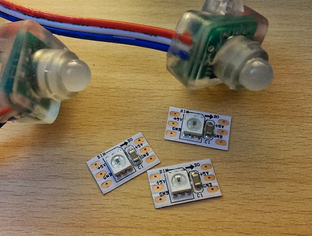
The NeoPixels themselves come in a wide variety of form factors, from individual LEDs to being pre-mounted on a board, to long ribbons or chains. I found what I wanted at a significant discount from various eBay sellers and ended up purchasing two kinds: a handful of individually mounted LEDs and a chain of 50 that were covered with a diffuser to soften and disperse the light.
What makes NeoPixels Über-Awesome is that each pixel within a chain of them can be individually addressed by your code. That is, if you have a serial chain of 10 NeoPixels, your code sketch can have the first Pixel light up one color, the second light up another color, and the third... etc. all the way down the chain, all controlled from a single pin from your microcontroller. "Ordinary" RGB LEDs connected to a single pin would all show the same color because the pin would only be able to control the entire chain as a whole. This can lead to some amazing effects even though the wiring is relatively simple. An entire string of NeoPixels requires only three connections: power, ground, and a single wire data/clock channel. (Note that there is a different kind of RGB pixels distinguished by the fact that they require separate pins for the clock and data, in addition to the power and ground lines. You may see reference to the WS2801 driver for these kinds of pixels)
The details of how this is accomplished by the microcontroller are far beyond the scope of this blog post (but explained nicely in this Sparkfun WS2812 Tutorial), but one of the great things about the Arduino community is the existence of publicly available code libraries that do all the hard work of making neat stuff happen. You just have to include the library in your sketch and learn some syntax for how to call the various functions. For these NeoPixels, the go-to library is of course the Adafruit NeoPixel library. This library also includes a good sample sketch called "strandtest" that demonstrates the library functions and this page in the überguide breaks down the strandtest sketch and explains how these functions work.
Over the weekend, I started trying to put together a basic circuit using the long 50 NeoPixel strand. I wired everything up in accordance with the tutorials I found, using a separate power source for the LED strand because the current draw for all 50 LEDs would be significantly more than the Arduino Uno I was using could muster. One tricky part was figuring out how to load the Adafruit NeoPixel library into Codebender. I followed the instructions to do this from a Codebender support page and uploaded the example strandtest sketch to the Arduino and... nothing!
The troublesome part was that there were multiple possibilities for why it wasn't working: perhaps there was a loose connection somewhere, or the power supply wasn't providing enough current or voltage, or I had a wire in the wrong pin, or there was an error in the sketch (though not one that was caught by the compiler). And so I spent a long, frustrating night trying to debug everything to find what was wrong, switching components, testing with the other kind of LED, and finally calling it quits at midnight with nothing to show for the time than a few brief flickers from one LED.
The next day I brought out the big (debugging) guns: a multimeter that a former student had given to me. It's an electronic tinkerer's best friend.
 I should have thought of using this the previous night. With the multimeter, I was able to determine that the circuit was fine, all voltages were as they should be, with the exception of the data pin from the Arduino, which wasn't outputting anything. This led me to conclude that there was something wrong with the code, and I began to suspect that it had something to do with the workaround way of including custom external libraries in Codebender. On a hunch, I installed the original Arduino IDE, loaded up the Adafruit NeoPixel library for it, uploaded the strandtest sketch to the Arduino again, and then sat back to enjoy the light show.
Acronym Glossary:
LED - Light Emitting Diode
RGB - Red Green Blue, for the three individual color LEDs that actually make up the RGB LED
SMD - Surface Mounted Device
| Close up of SMD 5050 showing the integrated WS2812 IC and separate RGB LEDs |
The NeoPixels themselves come in a wide variety of form factors, from individual LEDs to being pre-mounted on a board, to long ribbons or chains. I found what I wanted at a significant discount from various eBay sellers and ended up purchasing two kinds: a handful of individually mounted LEDs and a chain of 50 that were covered with a diffuser to soften and disperse the light.
What makes NeoPixels Über-Awesome is that each pixel within a chain of them can be individually addressed by your code. That is, if you have a serial chain of 10 NeoPixels, your code sketch can have the first Pixel light up one color, the second light up another color, and the third... etc. all the way down the chain, all controlled from a single pin from your microcontroller. "Ordinary" RGB LEDs connected to a single pin would all show the same color because the pin would only be able to control the entire chain as a whole. This can lead to some amazing effects even though the wiring is relatively simple. An entire string of NeoPixels requires only three connections: power, ground, and a single wire data/clock channel. (Note that there is a different kind of RGB pixels distinguished by the fact that they require separate pins for the clock and data, in addition to the power and ground lines. You may see reference to the WS2801 driver for these kinds of pixels)
The details of how this is accomplished by the microcontroller are far beyond the scope of this blog post (but explained nicely in this Sparkfun WS2812 Tutorial), but one of the great things about the Arduino community is the existence of publicly available code libraries that do all the hard work of making neat stuff happen. You just have to include the library in your sketch and learn some syntax for how to call the various functions. For these NeoPixels, the go-to library is of course the Adafruit NeoPixel library. This library also includes a good sample sketch called "strandtest" that demonstrates the library functions and this page in the überguide breaks down the strandtest sketch and explains how these functions work.
Over the weekend, I started trying to put together a basic circuit using the long 50 NeoPixel strand. I wired everything up in accordance with the tutorials I found, using a separate power source for the LED strand because the current draw for all 50 LEDs would be significantly more than the Arduino Uno I was using could muster. One tricky part was figuring out how to load the Adafruit NeoPixel library into Codebender. I followed the instructions to do this from a Codebender support page and uploaded the example strandtest sketch to the Arduino and... nothing!
The troublesome part was that there were multiple possibilities for why it wasn't working: perhaps there was a loose connection somewhere, or the power supply wasn't providing enough current or voltage, or I had a wire in the wrong pin, or there was an error in the sketch (though not one that was caught by the compiler). And so I spent a long, frustrating night trying to debug everything to find what was wrong, switching components, testing with the other kind of LED, and finally calling it quits at midnight with nothing to show for the time than a few brief flickers from one LED.
The next day I brought out the big (debugging) guns: a multimeter that a former student had given to me. It's an electronic tinkerer's best friend.

Acronym Glossary:
LED - Light Emitting Diode
RGB - Red Green Blue, for the three individual color LEDs that actually make up the RGB LED
SMD - Surface Mounted Device
Friday, September 13, 2013
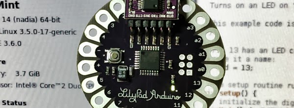
Learning with the Lilypad Protosnap Development Board

Here is the codebender embed of the Protosnap Development Platform Test Code.
I also put together a very rough and rambling video demonstrating the board running this sketch. One of the really neat things is the serial monitor that allows the Arduino to communicate things back to the computer. In this sketch, the serial monitor is programmed to display the real-time status of various switches and sensors. I show this in the video below. There is certainly a sense of satisfaction in getting lines of code to do some visible and interactive functions.


.png)

